VHF UHF Transverters
Updated
13-Dec-2019 03:14
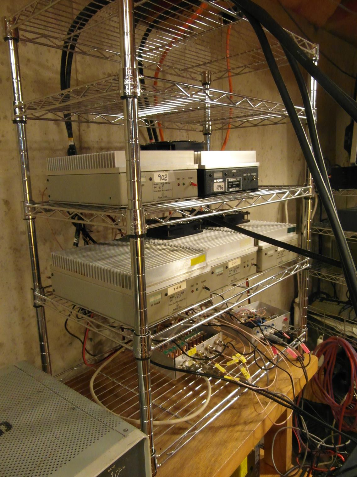
VHF / UHF Transverter stack
DEMI / Q5 Signal transverters for 144, 222, 432, 902, and 1296 (Q5 Signal).
Each is 28 MHz in and 50-60 watts output, and interfaced to my Apache Labs Anan 100D which is located in the upstairs shack.
Ultimately the transverter stack will be located in the garage near the VHF tower base, to minimize feedline losses.
The open collector outputs of the 100D are used to control the switching of the transverters.
At the bottom of the rack are two homebrew electrical subsystems.
The left one switches the TXIF and RXIF signal paths, and the right one switches the PTT control.
---------------------------------------------------------------------------------------------------------------------------------------------------------------------------------------------------------------------------------------------------------------------------------
Transverter System Block Diagram
---------------------------------------------------------------------------------------------------------------------------------------------------------------------------------------------------------------------------------------------------------------------------------
VHF / UHF Transverter Stack
I thought about building a rack out of aluminum stock to hold the transverters.
The advantage would have been a more compact rack unit, but the labor would have been extreme as would the cost.
So, a standard set of wire racks from Home Depot or BJs was used.
---------------------------------------------------------------------------------------------------------------------------------------------------------------------------------------------------------------------------------------------------------------------------------
System Block Diagram of PTT, TXIF, RXIF Switching
Cable 1 connects to the rotary switch (temporary) or the 100D Open Collector Interface (ultimate).
Cables RXIFC6 and TXIFC6 connect the RF path switches to the PTT switch unit where all the relays are interconnected.
---------------------------------------------------------------------------------------------------------------------------------------------------------------------------------------------------------------------------------------------------------------------------------
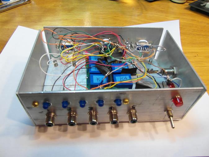
The chassis for all the Transverter Interface units is constructed from 2 inch aluminum angle stock, cut to length, and bolted together with #10-30 machine screws through tapped holes in the angle stock.
I will eventually use thin aluminum sheet, or perforated aluminum sheet, to make covers for these units.
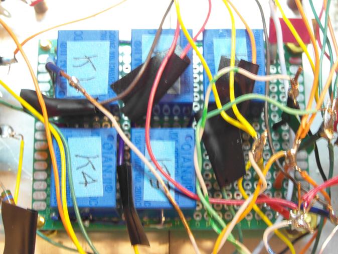
Detail of PTT Switching
These relays were acquired at a local hamfest and provide plenty of isolation for PTT switching.
Since they are only switched when a band change occurs, latency is not an issue.
---------------------------------------------------------------------------------------------------------------------------------------------------------------------------------------------------------------------------------------------------------------------------------
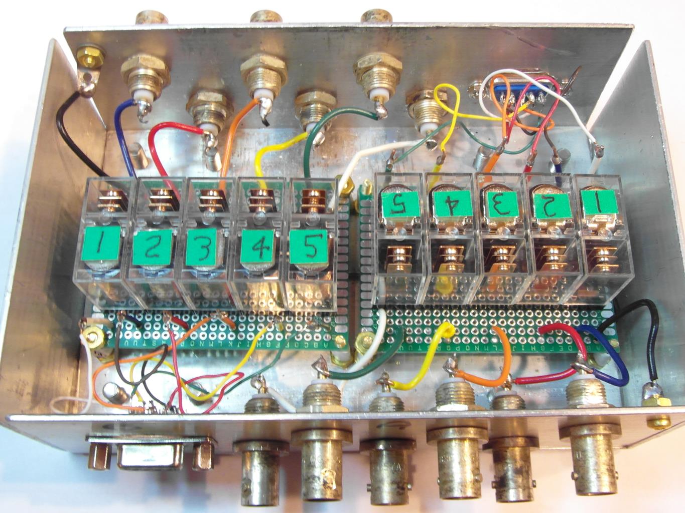
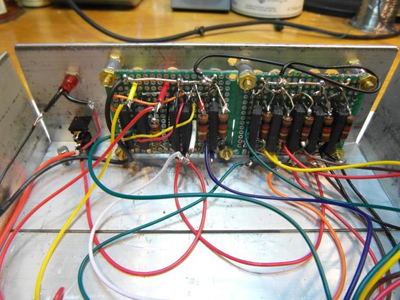
Detail of TXIF and RXIF Switching
These relays were acquired at a local hamfest and only provide about 40 dB isolation.
Since they are only switched when a band change occurs, latency is not an issue.
This is OK for the TXIF, but for RXIF some feedthrough from the other transverters occurs.
This is troublesome for local stations that totally pin the S-Meter since S9+60 attenuated by 40 is still S9+20!
I will be looking for a better RXIF switch with more attenuation, but this works in the meantime.
---------------------------------------------------------------------------------------------------------------------------------------------------------------------------------------------------------------------------------------------------------------------------------
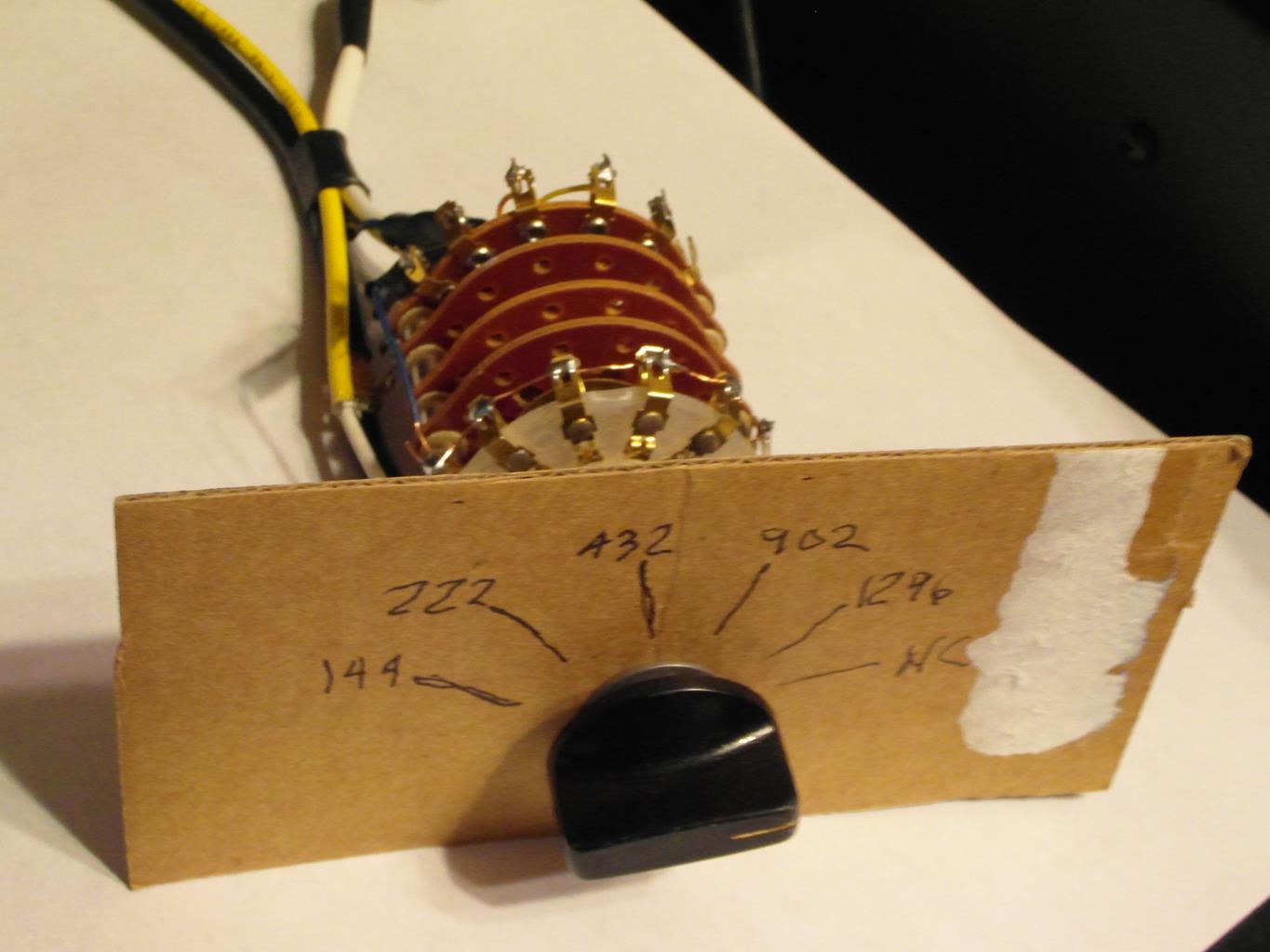
Manual Switching Unit
A rotary switch is temporarily being used to switch between OFF (HF+6) and one of the transverter units.
PTT is also switched between the HF amplifier and the transverter stack.
Ultimately this will be controlled by the Apache Labs Anan 100D open collector outputs.
---------------------------------------------------------------------------------------------------------------------------------------------------------------------------------------------------------------------------------------------------------------------------------
Automatic Switching Unit
This unit interfaces the Apache Labs Anan 100D open collector (OC) outputs to the transverter stack, and the HF amplifier PTT.
When in HF, the PTT needs to operate the HF amplifier.
When in VHF/UHF, the PTT needs to operate one of the VHF/UHF transverters.
Optical Isolator Solid State Relays (MOSFET) devices (ISYX CPC 1308Y NO/1309Y NC) are used to avoid possible ESD feedback over the moderate to long control lines between the transceiver and the transverters.
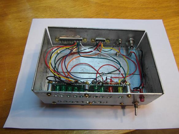
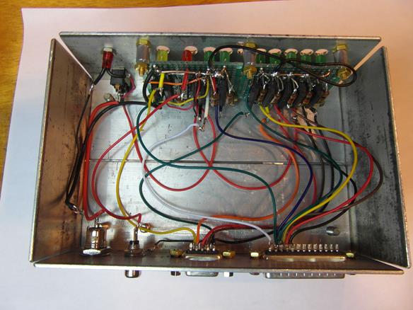
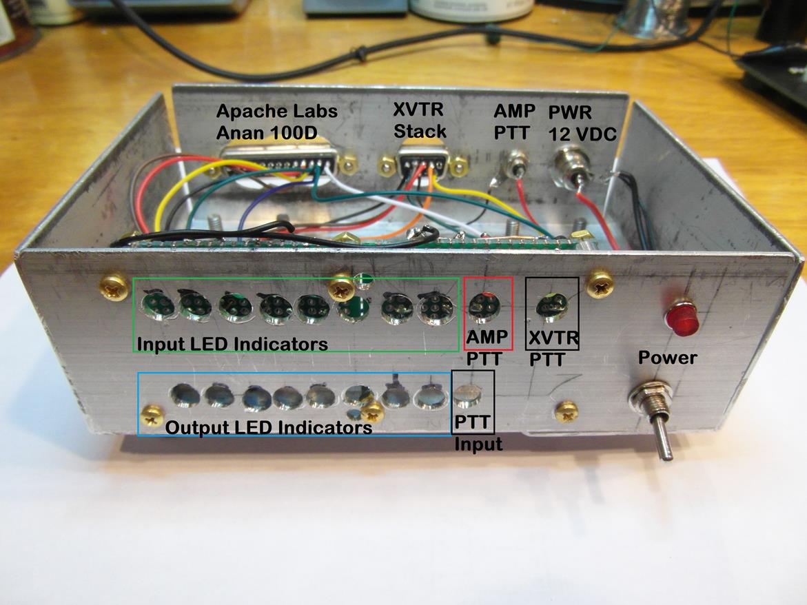
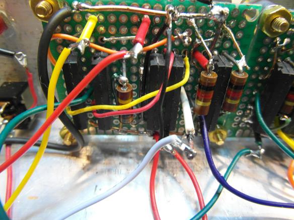
Overview of the SDRIF
Automatic Switching Unit
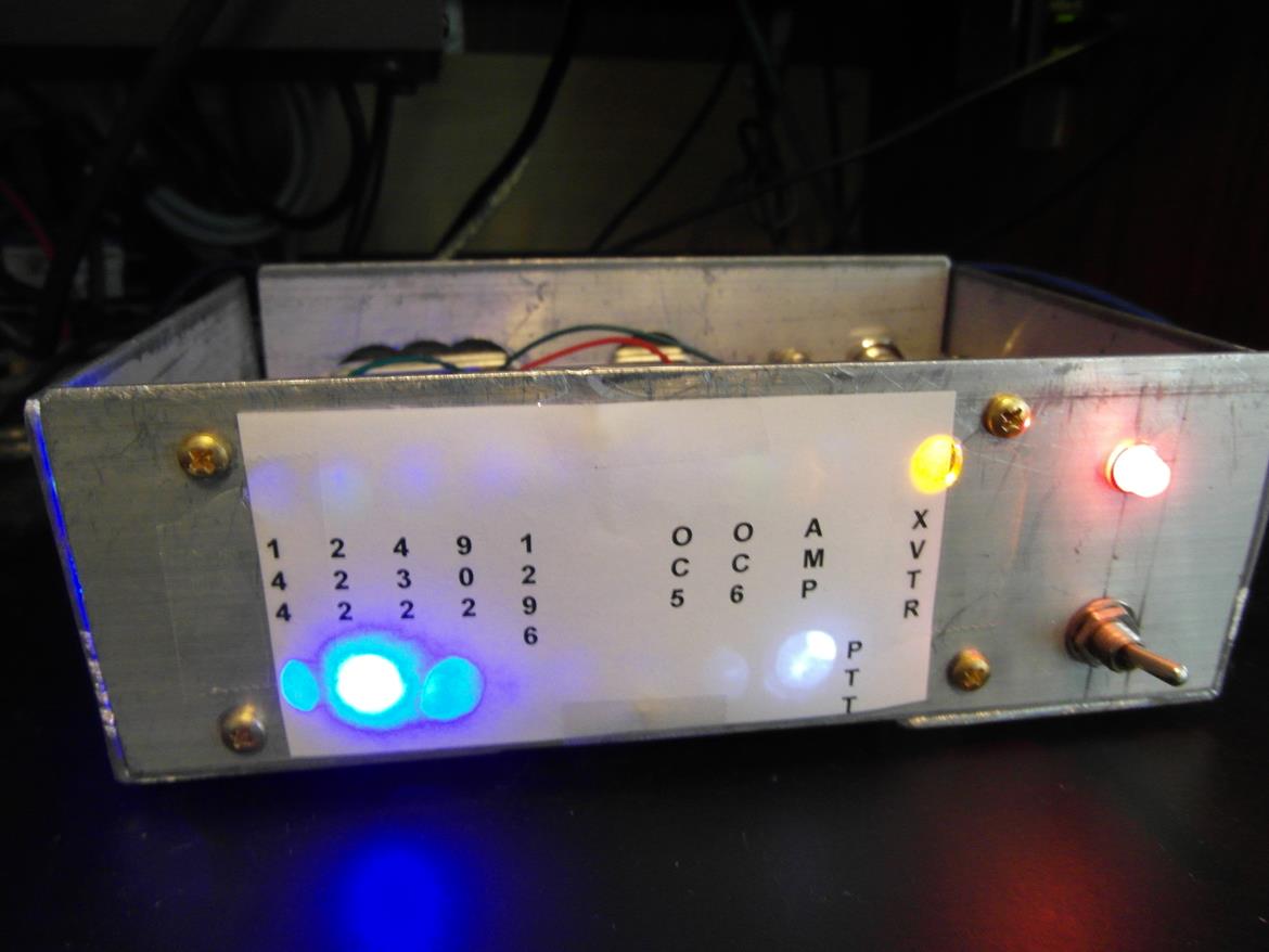
Input green LED indicators are along the top to the left.
Output blue LED indicators are along the bottom to the left
The red LED indicator is the amplifier PTT output indicator, top right, 1st LED.
The yellow LED indicator is the transverter PTT output indicator, top right 2nd LED.
The white LED is the PTT input indicator, bottom right.
The power ON LED indicator is above the power ON switch to the right.
---------------------------------------------------------------------------------------------------------------------------------------------------------------------------------------------------------------------------------------------------------------------------------
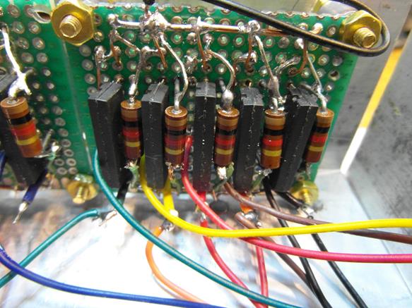
Details of the SDRIF
Automatic Switching Unit
---------------------------------------------------------------------------------------------------------------------------------------------------------------------------------------------------------------------------------------------------------------------------------
Circuit Diagram of
PTT Control and Circuit Board Layout
---------------------------------------------------------------------------------------------------------------------------------------------------------------------------------------------------------------------------------------------------------------------------------
Circuit Diagram of
Transverter Band Switching Modules (6 units)
---------------------------------------------------------------------------------------------------------------------------------------------------------------------------------------------------------------------------------------------------------------------------------