Mobile HamStick 4.6 MHz Antenna
Updated
16-Mar-2020 11:58
By
Terry G. Glagowski W1TR
[back to W1TR Antennas and QTH]
Introduction
This page describes how to modify a 75 meter HamStick antenna for use on the 4.6 MHz. This was accomplished by removing 350 turns from the top of the closely wound loading coil. This changed the center of the 200 KHz wide operating range from 3865 to 4600 KHz.
Construction Details
1. Remove approximately 13 inches of the black plastic shrink wrap from the top of the HamStick, thereby exposing the wire of the loading coil.
2. Unsolder the loading coil from the connector fastened to the whip (whip connector).
3. Remove 350 turns of wire from top of the closely wound loading coil which is about 32 turns per inch (TPI).
4. Use electrical tape to fasten the closely wound loading coil so it won’t come loose.
5. Rewind the loosely wound part of the loading coil which is about 1 TPI until it reaches the whip connector.
6. Use electrical tape to fasten the loosely wound loading coil so it won’t come loose.
7. Remove the enamel insulation from the loading coil wire where it will be soldered to the whip connector.
8. Resolder the end of the loading coil wire to the whip connector.
9. Wrap the exposed part of the loading coal with black vinyl electrical tape, starting from the bottom (or use heat shrink material). Starting from the bottom will cause the edges of the tape to be on the lower part of the spiral of tape layers, hopefully the weather will follow gravity downward?
Development Methodology
I started the development of this antenna by measuring the frequency range of operation before modification so that I knew what my starting point was. When the adjustable whip was fully extended, the center frequency of the antenna was about 3750 KHz. When the adjustable whip was fully retracted, the center frequency was 3960 KHz. It should be noted that it is possible to retract the whip further, but doing so will cause the bottom of the whip to enter the closely wound part of the loading coil. The manufacturer warns that this could cause excessive heating and may damage the antenna. Another side effect is that the metal (steel) whip will cause the inductance of the coil to increase (high permeability of the whip), so that as the whip is retracted beyond that point, the frequency gets lower not higher as you might expect (due to increased coil inductance offsetting the shorter whip). One could cut part of the whip off and make the frequency higher, or simply operate without the whip at all, but that is not what I chose to do. Even if the whip were totally removed, the operating frequency of the antenna would still be too low for the 4.6 MHz frequency.
First, I investigated the mechanical construction of the HamStick to see how the modification could be made. The stick is constructed from a 3/8” diameter fiberglass rod fastened to a 3/8“ x 24 TPI threaded male mount at the bottom, and a 3/8“ x 24 TPI threaded female mount at the top. A 3/8” x 24 TPI fitting that has dual set screws allows a 1/16” steel whip to be installed and adjusted for length. The loading coil is closely wound on the middle of the fiberglass using about #20 or #22 wire closely wound at about 32 TPI. A portion of the loading coil at the top and the bottom is wound loosely at about 1 TPI. A plastic covering (heat shrink wrap?) covered the entire loading coil for weather protection.
I removed the top portion of the plastic covering and found that the end of the loading coil wire had been soldered to the top 3/8” x 24 TPI threaded female mount and filed down to make the fitting smooth. I carefully used a knife to cut a slit in the covering along the length to be removed, and then a circumferential cut to remove that section. Be careful not to damage the coil wire underneath. A small groove had been cut into the mount so that the wire would fit into it, and soldering would work well. I unsoldered the wire from the mount being careful not to overheat it and loosen it from the fiberglass. I then made my coil modifications described below and resoldered the end of the loading coil wire to the mount.
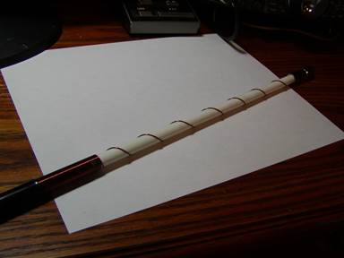
Picture of the Loosely Wound Loading Coil, #22 wire, 1 turn per inch, between the closely wound coil and the threaded mount.
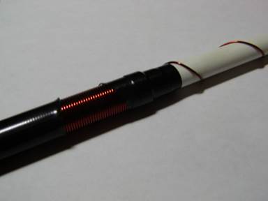
Close Up of Closely Wound Loading Coil, #22 wire, 32 turns per inch.
Note the electrical tape used to keep the coil from coming unwound after the plastic weather shield was removed.
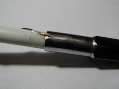
Close Up of the Soldering Point of the Loading Coil Wire to
the Female 3/8” 24 TPI threaded mount.
Note the groove in the mount for the wire to fit in.
Determining the Number of Turns
Before the modification, I set the stock whip (without cutting it) at the midpoint of the operating range (midpoint between the minimum and maximum resonant frequencies of the standard HamStick by adjusting the whip only) and found the center of the antenna operating range to be 3865 KHz. I then removed 20 turns of the closely wound coil to see how much that changed the frequency. The new frequency was 3895 KHz, a change of 30 KHz for a change of 20 turns, or 1.5 KHz per turn. A quick extrapolation would predict that I should remove (4600 – 3865) / 1.5, or 490 turns, but the inductance of a coil is proportional to the square of the number of turns (N2) not the number of turns N, so this is way too many turns. I removed another 100 turns from the coil and the frequency was 4050 KHz. This time the rate of change was 1.55 KHz/turn, a little higher as was expected. I then removed another 200 turns from the coil and the frequency was 4500 KHz, it was possible to shorten the whip to minimum and be at 4600 but I wanted that to be the center of the new operating range. At this point, the rate of change was 2.25 KHz/turn, so I extrapolated that 44 more turns should be removed. Knowing that a linear extrapolation would be too high, I removed only 40 turns. The frequency was then 4620 KHz, a little too high by about 25 KHz, but easily tuned by extending the whip about an inch. At this point, I had removed 20+100+200+40 = 360 turns and the rate of change was 3 KHz/turn towards the end of this process, so the right answer was to remove only 352 turns (360-(25/3) = 351.66 turns, or rounded to 350 turns. This should set the midpoint of the new operating range at about 4590 KHz. I measured the SWR to be just below 2:1, a little higher than the original HamStick down at 3865 KHz. My mobile installation consists of an Icom IC-7000 and an LDG AT-7000 antenna tuner, so getting a perfect match to the transmitter is no problem.
Conclusion
In retrospect, it should be considered that a short antenna loaded at the middle has higher efficiency than one loaded towards the bottom, although the amount of loading inductance needs to be a little higher. There are tables and formulae in handbooks and journal articles about this. At the next hamfest, I might get another 75 meter HamStick and try the modification again, but remove the turns from the bottom of the loading coil rather than the top. I would expect fewer turns to be removed and maybe the SWR would be a little lower with a loading coil more near the middle of the whip. To see my point, take a look at a 40 meter HamStick and observe that the construction is very similar to the 75 meter one, but turns have been removed from the bottom!
Immediately following the fabrication of the 4.6 MHz HamStick, I made an on the air test by checking into the 1S1 evening net on 04-Jul-2008. I got excellent signal reports. The band had good short and medium skip to New Hampshire, New Jersey, and Pennsylvania so stations there were loud and clear, but the signals to the western end of the region at Indiana and Michigan were fair to weak readable. This was clearly a successful project, and I hope that my lessons learned will benefit others in adding a mobile / portable / emergency capability to their station.