New VHF/UHF Tower
Updated
16-Apr-2025 17:49
[back to W1TR Antennas and VHF Beams]
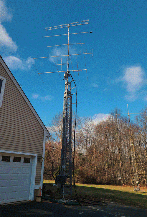
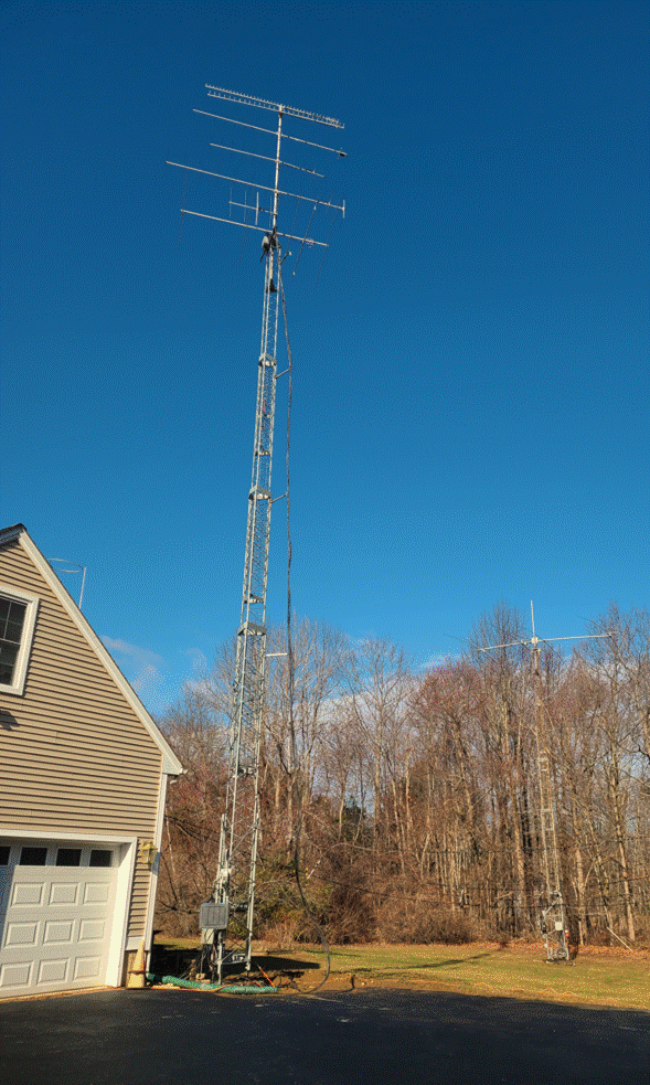
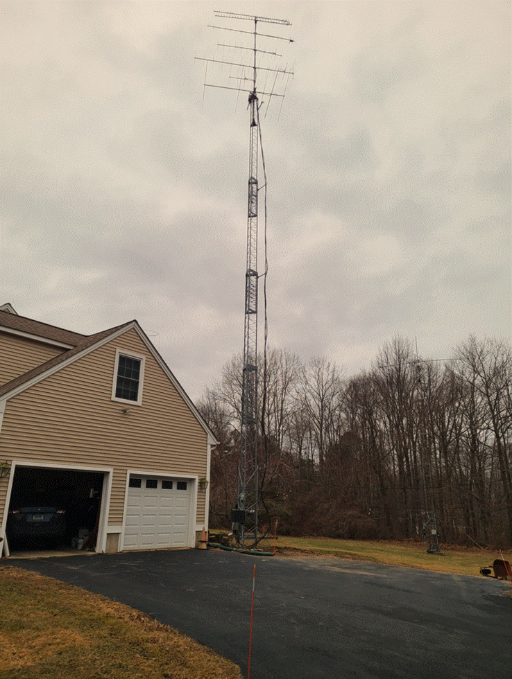
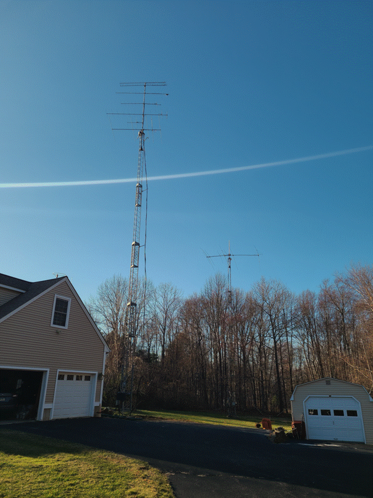
VHF Yagis for 6m thru 1296 MHz are shown here mounted on a 2 inch OD aluminum mast in the LM470 tower cranked up to about 70 feet.
A Yaesu G-1000 DXA is used to achieve 450 degree rotation, avoiding a dead spot.
The antennas from bottom to top are:
· 6 m, 50 MHz, 5 elements: K1WHS design 5 el on 17 foot boom August 2018 (picture far right below)
· 2 m, 146 MHz, 4 elements: Vertically Polarized Beam for 2 Meter FM Operation, Unknown Manufacturer
· 2 m, 144 MHz, 15 elements: W1JR prototype JR Boomer, a Cushcraft 13B2 modified to have triple reflectors
· 222 MHz, 13 elements: Unknown manufacturer, similar to Cushcraft.
· 70 cm, 432 MHz, 19 elements: Cushcraft A719B
· 33 cm, 902 MHz, 33 loop elements: Microwave Associates
· 23 cm, 1296 MHz, 46 loop elements: Microwave Associates
In January 2024, a year long project was started to replace the 50 Foot VHF/UHF tower that crashed during a bad storm in late December 2023, just before Christmas.
More details TBD as the story
progresses.
Finding a Replacement Tower
During the Winter and Spring of 2024, I made numerous inquiries on the WEB and Radio Blogs (YCCC, CMARA, ECARA, VHF NewsGroup) regarding a replacement tower.
I got a lot of answers and advice, thank you to everyone.
What I really wanted was a second Tri-Ex Tashjian LM470 (70 foot tilt-over crank-up tower) like the one I use for HF.
This has a great design where the initial installation tilt-up was with the fulcrum at the bottom ,which was a difficult effort to crank the manual winch.
It has a maintenance tilt-over with a hinge at the 8 foot mark, and the tower partially balanced, making this effort much less.
One possibility was a crank-up / tilt-over tower mounted on a trailer, but the XYL didn’t want it in the yard (neither did I) but it would be great for Field Day!
They were anywhere from 80 to 100 feet high, but very expensive ($10K), and located in the state of Illinois (long drive with truck rigged for trailer).

Another was this (50 ft), located in Massachusetts, but I didn’t really like the looks of this one.

There were also a couple of LM470 type towers located in Minnesota and Upstate New York that might have worked out.
But I balked due to the transportation costs.
Ultimately I found this one in Somers, just 20 miles away from Ashford.
It was exactly what I wanted, a Tri-Ex Tashjian LM470, younger brother to my HF Tower, in excellent condition.
I actually knew the original owner (Steve Tripp / K1IIG) who passed away a couple of years back.
I used to work Steve on VHF contests regularly, especially on 1296.
George Collins / KC1V acquired the tower from Steve’s estate
but never got around to installing it.
The tower was stored at KC1V QTH in Somers:

Moving the Tower from Somers to Ashford Connecticut
In May of 2024, the deal to acquire the tower was completed, and the tower was moved from Somers to Ashford.
I enlisted Paul / KE1LI and his trailer, and John Parker, a Somers based septic contractor, to load and unload the tower using a fork lift loader.
It then sat on the side of the yard in Ashford until September when the base was ready for install.

Building Permit
In 2008 when I installed both towers for HF and VHF, the process was simple: Pay for the building permit and show the plans to the building inspector.
Not So this time.
I went round and round regarding the specs and documentation for the tower.
The building inspector was a hard-ass.
I even had a previous engineering analysis that Tashjian prepared for Steve when he bought the tower.
The building department would not accept that, and required me to hire a licensed professional engineer to translate what was in that report to something the town would accept.
Cost me $$$$$.
Heaven help anyone who buys a
used tower and does not have the manufacturer’s documentation, especially an
engineering analysis report.
Engineers Report
After a number of inquiries and advice from YCCC, News Group, and K1VR, I found a professional engineer who could accomplish the task.
William Shaheen / N1CQ, who lives in Agawam, MA and is licensed in CT created the report and closed the loop with the town.
Once again: $$$$$ but successful.
Foundation Base Hole
I was fortunate to have a neighborly neighbor down the street, Kenny Deal, who has some construction equipment.
He agreed to dig my foundation hole for the new tower base (for free, but I reimbursed him for the use of his equipment anyway).
The new base is located just east of the previous one near the corner of the garage.


The hole is 7 feet deep and 4 by 4 feet, sort of…
Yes, we had some rain after the dig before the concrete was poured.
Most of it dried out but not 100%, not to worry.


Base Concrete
The base installation was done by VCT Towers of New Hampshire, associated with K1RX.
Some additional REBAR was added to the stock base that came from Tri-Ex Tashjian, per the town building inspector.
The concrete pour was done in 2 stages, first a footer was poured to hold the REBAR and BASE perfectly vertical before the main pour.


About 2 or so cubic yards of concrete were mixed in a wheel barrow and poured as a footer to keep the REBAR assembly stable for the final pouring.


After a couple of weeks, the VCT guys came back and installed wooden forms for the final pour to assure a square foundation base.
This required about 9 cubic yards to fill the hole, with less than 1 cubic yard left in the truck… good estimation.


Some graffiti were added to finish the job.

Mounting the Tilt-Over Accessory
In late Sepember, after a couple of weeks of letting the concrete cure, Ed / K1ZE came over to help me mount the tilt-over accessory onto the base.
He also helped me remove the wooden forms.


Moving the Tower to the Tilt-Over Accessory
In early October, after another couple of weeks, Ed / K1ZE and Paul / KE1LI came over along with my neighbor Kenny Deal (with the fork lift) and moved the tower to the base / tilt-over accessory.
Raising the Tower
The tower weighs about 1200 pounds, and with the fulcrum at the bottom, even with a heavy-duty winch, the effort to raise the tower to vertical was quite a lot.
Ed and Paul took turns cranking it and alternately resting.
Fortunately, in maintenance tilt-over mode, the hinge is at the 8-foot level and the tower is partially balanced for tilt-down and tilt-up.


Tilt-Over Winch
I motorized the maintenance tilt-over with a Harbor Freight 110 VAC winch to make this effortless (same for the HF Tower).


I modified the connection between the tilt-over cable and the tower so that only the bottom tower section is connected.
This allows the tilt-over cable to remain attached while the tower is cranked up and down.
Previously, a cable link was wrapped around the legs of the lower two tower sections.
This modification was accomplished by drilling a 3/8-inch hole through a leg of the bottom tower section, and inserting an eye-bolt and a coupling link / carabiner to attach the tilt-over cable.
This capability be useful during installation of the rotor and rotor plate, to give the top section a little more accessibility by raising the tower slightly before tilting down.


Clearly, this was NOT a good
idea.
The eye-bolt was not strong enough for the forces applied and bent.
I almost lost the entire tower as a result.


I also decided that it would be best to replace the corroded cable used for tilt-over.

Tilt-Over Test Ride
It was windy for a couple of days, and since it was the first test of the tilt-over, I decided to procrastinate and work on other tasks.
Then it finally went for a test ride.
The winch worked perfectly, and all I did was watch and press the buttons on the control box.
UP was just as smooth a ride as DOWN.
I was not sure if the tower had a thrust bearing when I acquired it, but I’m sure of it now.
I tested it and the bearing works AOK (I had a spare from the 50-foot tower that broke just in case).
As it turns out, it is possible to back both cars out of the garage with the tower tilted over. 😊
The car in the right side is 5 feet tall and the tower low point is 5 feet 8 inches high and it will clear the mast and antennas when tilted down.
The car in the left side of the garage will be trapped until the tower is tilted up a bit to clear the antennas when they are installed. 😉


Crank-Up Motor Replacement
While testing the crank-up winch motor, I discovered that it had become defective. ☹
When we initially stood the tower up vertically, Paul and Ed noticed that water came pouring out of it.
So, the weather probably got into it when it was stored in Somers for a couple of years, or even here in Ashford for a few months.
The stock motor was a Leeson WashGuard Model C6C17WB2M, Cat No. 112432, made in Wisconsin.
An exact replacement was available from Electric Motor Wholesale in Delaware for about $500.
Google is your friend… and although AD tracking can be annoying, sometimes it helps you.
An AD showed up saying that Amazon had an exact equivalent made by Vevor (☹ China) for only $152.
I decided to go with that one.
When it arrived, I opened up the electrical connections and wired it up to test the Clockwise and Counter Clockwise functions.
It worked great on the bench, now I have to install it on the tower.
The old motor went to the dump (transfer station) after removing some possibly useful hardware (yes, I’m a pack rat).


Tower to Motor Wiring
The wiring was ever so slightly different from what I was expecting in the tower control box wiring.
I had to document, decipher, and understand the existing wiring, and make a small modification.
The main difference is that the HOT POWER wire goes directly to the motor and not one of the switch common contacts,
and the INS connection from the motor goes to the UP/DOWN switch instead.
6 wires are needed for this instead of the original 5 wires, so a new 6 conductor cable was required.
The original and revised wiring are shown below.
The cable to the motor has been wired and tested on the bench.
In the next day or so, I will mount the new motor on the tower, wire it up, and test the motor (without the pulleys).
Then I will attach the pulleys and belt, and take the tower for a test ride UP and DOWN.


Motor Mounted to Tower
The new motor is now mounted to the tower where the old one was.
The wiring was complete from the motor to the tower control box according to the above diagrams.
However, there was a slight problem.
The motor would not turn clockwise (UP), but did work counter clockwise (DOWN).
I measured the UP limit switch with an ohm meter and discovered it was open when it should be normally closed, and open only when the limit switch is triggered.
I then jumpered it for a test.
The motor turned clockwise (UP) with the jumper in place.
This will require tilting the tower down again to diagnose the limit switch.
The contacts inside the limit switch assembly were dirty and could not be cleaned or repaired, so a replacement was ordered.


Pulleys and Belt Installed
Both pulleys were installed, as was the belt.
The smaller pulley on the motor was aligned with the larger pulley using the set screw.
The belt is very tight but works OK.
A short test to raise the tower a couple of feet and then lower it to test the down limit switch was carried out.
It was too windy today to do the full crank-up test.


Tower Base Junction Box
The Tower Base Junction Box joins the coaxes from the house / shack with those going up the tower.


Rotor and Mast Installation
The rotor and mast installation went well, with a little finagling of the mast with the rotor.
It turned out that the ring from the old thrust bearing was rusted on to the mast and I had to cut it off with a cutter / grinder.
The set screws were also frozen in rust.


I first mounted the rotor plate in the tower, then bolted the rotor to the plate.
With the help of XYL Lyn, I was able to “thread the needle” of inserting the mast into the rotor mount assembly while she held the far end of the mast.


It was getting dark, so I tilted up the tower, but all the bolts needed to be fastened down a bit better.
Sometimes tilting the tower up and letting parts settle into their resting position is a good idea before tightening things down, which I did the next day.


Tower Top Junction Box
The junction box at the top of the tower joins the coax runs from the junction box at the tower base to those going to the antennas around the rotor loop.


Top Junction Box Modified due to tight quarters.
I needed to change out some of the UHF barrel connectors for longer ones, and
one of the N-Connector barrel connectors as well,  so that coax installation is easier since the
TOP JCT box is quite small.


Crank-Up Test Ride
To perform the Crank-Up Test Ride, the tower must be secured to the tilt-over accessory and tower base.
This is not easy since unlike in the text books and documentation because the mounting holes don’t always line up perfectly.
Some finagling is necessary using a scissors jack and a SPUD wrench to line up the holes to insert the bolts.
For the test ride, only 6 of the 15 bolts were inserted to save time since there was no wind.
Due to the late hour and the onset of dusk, the test ride was deferred to the next day.


Today the tower went for a crank-up test ride with the mast and rotor installed, but no antennas yet.
The motor had a tough time raising the tower, indicating that something was not aligned right.
I see a slight deformity due to wind stress at some time in its life.
I think it will be useable though.


Antenna Installation
All antennas were mounted onto the mast.
The new 2m antenna has a broken element, but I have a replacement from the old 2m antenna.
The 222 boom is slightly bent and some elements are bent / broken, but I have material from the old 2m antenna that can be used to fabricate new ones.
One of the 432 elements is bent, not sure if it is serious enough to replace it, but I have material from the old 2m antenna to do so.
The coax needs to be installed to complete the installation.
There are junction boxes at the base and top of the tower.
Coax needs to be connected from the shack to the base JCT, the base JCT to the top JCT, and the top JCT to the antennas.


Coax Installation
Base JCT to Top JCT

Coaxes from the Base JCT to the Top JCT were easily connected after fabrication.
LMR 400 (low loss, not flexible) was used.
Each coax was color coded so that mistakes in connecting them would be minimal.
1296 was WHITE
902 was VIOLET
432 was BLUE
222 was GREEN
144 Horizontal was YELLOW
144 Vertical was ORANGE
50 was RED.
Top JCT to Antennas and Rotor Loop
Coaxes from the TOP JCT to the Antennas have been connected to all 7 antennas.
This was completed two days after Christmas Day when the weather was above freezing, little or no wind, and sunny.
Details of the Top Junction Box, and the Rotor Loop.


Antenna Repairs
Several of the antennas need minor repairs with bent or broken elements.
The new 6m Yagi needs to be re-tuned to 50.200 MHz using a better antenna analyzer or Mini VNA.
The old 6m Yagi was damaged in the tower fall, but is possibly reparable.
The new 6m Yagi has a 12 foot boom whereas the old one had an 18 foot boom, which provide a few dB more gain.
I will try to repair the larger 6m beam in the Spring, and hopefully have it back on the air.
One of the new 2m horizontal Yagi elements is broken,
It was replaced with one from the old 2m antenna
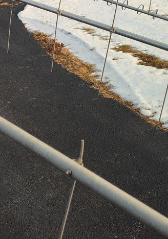
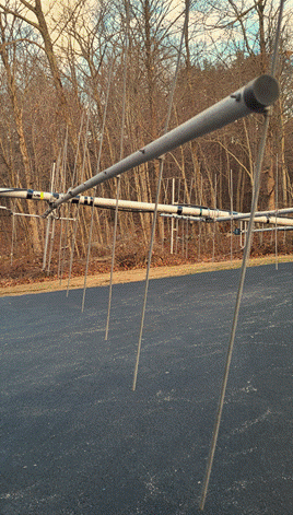
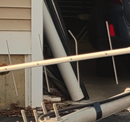
Several of the 222 MHz Yagi elements are broken or bent.
I was able to straighten one of the elements, another broke while straightening and had to be replaced, and the third was already broken and replaced.
Elements from the old 2m beam were cannibalized and cut to size using a jig saw.
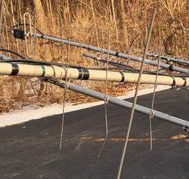
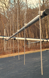
One of the 432 MHz Yagi elements is bent.
I straightened it, carefully, since these elements are kind of brittle.
Final Tilt-Up and Crank-Up
It is New Year’s Eve and a bad storm is expected, so final crank-up will not be done until after that has subsided.
I did not quite make my goal of getting the tower finished before snow flies…
But it is pretty much done before end of year 2024.
All 15 bolts in the tower base were installed today (10-Jan-2025) and ready for Crank-Up.


Not the final crank-up to 70 ft, but about 60 feet just before the Jan VHF Contest.
Transverter Stack
Final Crank-Up is pending On-The-Air Testing of the antennas and transverter stack.
Testing of the transverter stack was a mixed bag (09-Jan-2025)
Initially the 222 MHz transverter RX was working from the XVTR to the 7000DLE.
But the other transverters were not working.
Reverting back to the 222 XVTR, that was no longer working !
I suspect that there is a cabling / connector problem in the test setup.
![]()
The following sections TBD
when the work is finished.
Uh-Oh!
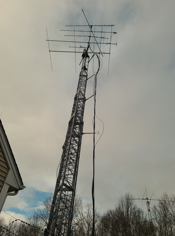
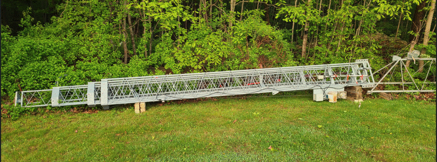
The 1296 looper Yagi came loose during high winds during late February 2025.
This will require lowering and tilting the tower down to fix this.
Problem Fixed
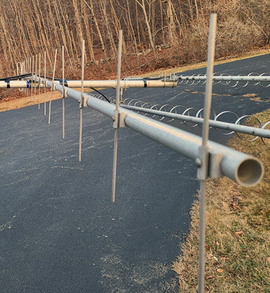
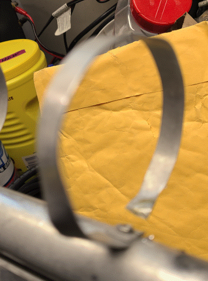
I ended up ordering replacement looper elements for the 902 and 1296 Yagis which got broken,
and a new set of feed point components for the 1296 Yagi.
I also straightened out a couple of elements on the 222 Yagi that got bent in the process.
1296 Yagi

902 Yagi

When the weather finally cleared up and the parts arrived, they were mounted on the tower.
Fixed
Note: both the HF and VHF towers are 70 feet, but the HF is in the back yard farther away !
On-The-Air Testing
The 6m, 2m vertical (FM Repeater), and 2m horizontal (CW/SSB) antennas have been tested and appear to be working well, even with the tower telescoped down to 25 feet (plus 15 foot mast).
Initially, the 6m antennas (Yagi, Halo, and Vertical) all appeared to not be working, but later it was found to be a “cockpit error”,
the operating position switch for the 6m system was turned off.
On the air testing showed these 3 antennas are working well.
I was able to copy WZ1V on the coast (50 miles) on 222 so I know that antenna is also working.
432, 902/903, and 1296 willl require
the transverter stack to be back in operation, which will be the next task.
Mission Successful, time for a shot of 21 year Balvenie
single malt scotch whiskey!!!